
Progress on the restoration of XPO continues at a bimbling pace. After tearing down the engine block, I’ve returned to the cylinder head. Having previously overhauled the cylinder head, it was time to prepare the rest of the parts and maybe start putting some of the engine back together.
Returning the Tappets to the Cylinder Head
To let air and fuel into the cylinder, before setting it on fire, the inlet and outlet valves in the top of the cylinder need to open at the right time. The opening of the valves is controlled by the rotation of the camshaft. As the cam lobes rotate, they push down on the springs allowing the valves to open. Between the wide cam lobes and the narrow valve stem is the tappet. These are often shimmed to take up some of the variations in manufacturing tolerances.

The Mi16 engine uses hydraulic tappets which use oil pressure to auto-magically take up the gap between the camshaft lobe and the valve. Well, that’s how I understand it. The hydraulic tappets on this car are known to be sticking. This pretty much means they’re full of crud and need refurbishment to get the valve timing just right. To do this I’m using the guide from Taylor Engineering, and the original Citroen workshop manual which can be found on the BX16v Forum.
Dressing the buckets
The camshaft lobes are continually in contact with the top surface of the bucket, with movement lubricated by the engine oil. Over time the top of the buckets become warn in the middle, especially if the oil is not routinely changed. To make sure the buckets are serviceable before reassembly back into the cylinder head, they need to be dressed.
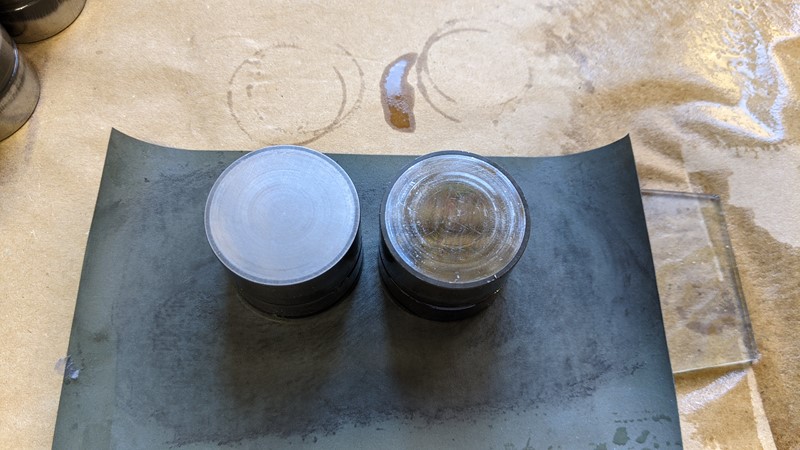
Dressing the buckets mean rubbing the tops of the buckets down as flat as possible. As per the Taylor Engineering guide, I’m using a few grades of wet and dry (starting with 800) on a piece of glass in a figure 8 movement. In the picture above the left-hand tappet has been dressed, losing the scratches and rings. The even finish lets me know the top is not dished through excessive wear. Only another 15 to go!
Priming the tappets
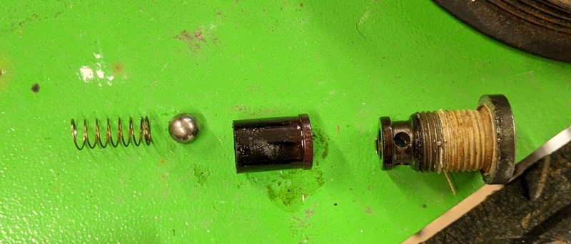
Continuing through the guide, the next step is to put the tappets back together. First the sleeve is topped up with oil, then the piston is placed into the sleeve and the ball spring depressed to let all the air out of the piston to only oil remains.
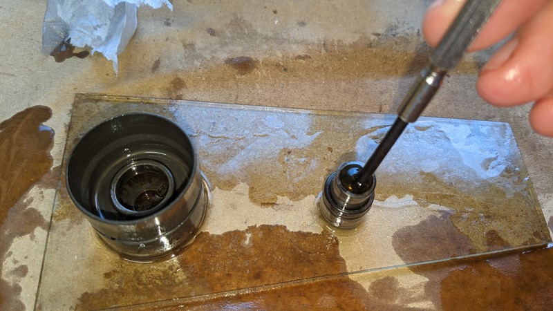
The workshop manual states ‘refit both the piston and sleeve, exerting a pressure on the assembly to cancel the circlip’. This is an understatement akin to that of the Haynes manual. The reality is, rather a lot of force is needed to overcome the circlip, and some swear words, preferably in French. I managed to stop at a hammer though!
Reassembly into the Cylinder Head
With the hydraulic tappets refurbished, it’s nearly time to start putting part together. However, before that, there is one last step in preparing the head. The camshafts sit in the journals in the head and once the engine is running they ‘float’ on a bed of oil, fed onto the top of the camshaft. I noticed when first taking the hydraulic tappets out of the cylinder head, that the journals were, in places, rather rough.
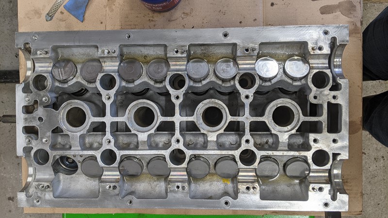
I have a suspicion that previous aggressive removal of the hydraulic tappet may have caused the rough edges, or perhaps they weren’t removed in manufacture. Either way deburring is easy enough with a sharp edge. Then the journals are finished with an application of 800 then 1200grit wet and dry. Once the head is cleaned for one final time, the hydraulic tappets can be dropped back in. A drop of oil helps to aid slide them home, and avoid any oxidisation.
Checking the relief valves
One thing that I did pick up on in the Citroen Workshop Manual was the presence of the pressure relief valves. The two valves sit at either end of the cylinder head, behind hex headed plugs. At first sight, they didn’t look too healthy.
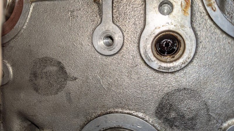
The manual states that the plastic valves should be removed by destruction (with a wood screw) and replaced with new ones. Well, they haven’t been available for a very long time, so I took a more careful approach.
Once out, it’s clear the valve is actually in good condition and cleaner than it looked while in the head. The plastic valve has changed colour having been saturated in dirty oil. No amount of cleaning in the ultrasonic cleaner will restore the original colour, so it goes back into the head and the cap is thread locked and tightened back up to the appropriate torque.
Polishing my shaft(s)
Reinstalling the camshafts and the cam caps is the next step in rebuilding the cylinder head. The camshafts that came out of the cylinder head aren’t looking the greatest and need a bit of refurbishment. The lobes and the camshaft journals in contact with other metals, they need to be well polished to avoid wear and loss of horsepower.
Poorly inlet shaft
The first shaft I take hold of is the one that drives the inlet valves. Initially, it just looks a bit dirty, but once the layer of built-up oil residue is removed, it’s clear the cam lobes aren’t happy. As can be seen in the picture below, the lobe tips are heavily pitted. It’s not something I’ve seen in a cylinder head before. The camshafts and especially the cam lobes are a very hard material, its not unusual to see their shape change due to wear, but pitting is definitely not a good sign.
It looks like the lobes have been left in water for a long time and rusted up. However, there is no evidence of pitting or corrosion anywhere else on the shaft. I do wonder if perhaps this damage is caused by high levels of friction between the cam lobe and a stuck hydraulic tappet. Or perhaps when the valves were previously damaged, they were so bent they couldn’t open. Either way, there is no chance of saving this camshaft, but fortunately, I have a spare!
Polishing Method
With the damaged part swapped out for a better one, it’s time to get to polishing the shaft. I don’t want it getting away from me, so I’m taking a firm grasp of the cold steel and ratchet strapping it down. All smut aside, the method I’m using to get a shine on my shaft means it needs to be well secured.
I’m using strips of various grades of wet and dry (600 to 2500), wrapped around the journal, then spun using a shoelace or piece of flat cord. This is something of an old school method. I don’t remember where I learnt it, but it works well. The use of the lace or cord helps to keep even pressure on the entire surface under the wet and dry. achieving an even finish and avoiding damage.
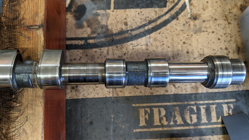
It takes time and patience to work along each of the journals. The cam lobes are a little trickier, they need to be done predominantly by hand so care needs to be taken to apply an even finish. My aim here is to take out most of the scratches and marks. There is little point in getting to a mirror finish. Removal of too much material will take the shaft out of spec and leave it rattling around like a pea in a cup.
Finishing off the shafts
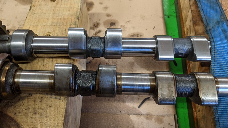
A few days later and the end result is pretty satisfying. In the picture below, the difference between the untreated and polished shafts is (hopefully) quite apparent. And compared to the damaged lobes on the original shaft, the replacement is looking much better. One more shaft to polish and they can go back into the cylinder head
A few more cylinder head parts to refurbish
In the excitement of polishing my shaft, I clean forgot about some of the other parts that needed cleaning. I also noticed something rather unexpected!
Snapped Cylinder Head Cover Bolt
When I was taking the engine apart, I noticed that one of the chrome rocker cover bolts where missing. What I hadn’t noticed was that some of the bolt thread was still in the hole! The scratching on the cylinder head makes me wonder if someone has attempted to remove the snapped thread before.
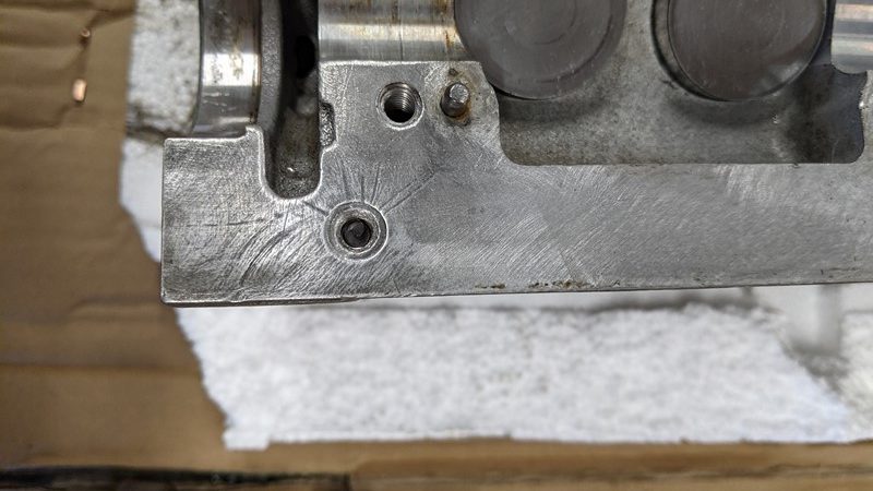
And there it is, just peaking out at the top. My preferred method for getting the stud out of the soft cylinder head is to drill a small hole through bolt, then slowly make it bigger until only the threads are left. Using a centre punch, I put in a mark on the top of the remaining thread and started drilling. The bolt instantly moved, downward. It evidently wasn’t as stuck as I expected.
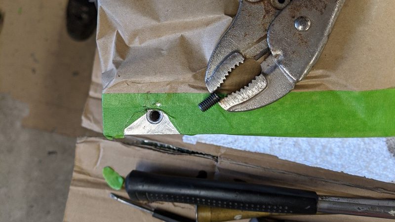
Using a small screwdriver and hammer, I was able to slowly tap the remaining thread around until it started backing out of the hole. Once there was a few mm out I could use the grips on it. Eventually, the snapped stud was freed from the cylinder head. And then went and bought a lottery ticket!
Camshaft Bearing Caps and Bolts
I also needed to clean the camshaft bearing caps. A quick trip into the ultrasonic cleaner and using the carbusonic solution for aluminium, and the camshaft bearing caps come out looking very shiny.

What surprised me was just how much filth was trapped in the camshaft bearing caps. I’m pretty glad I’m going to this level of cleaning, it should keep the engine on top form for a good while. The next step is to clean the bolts.

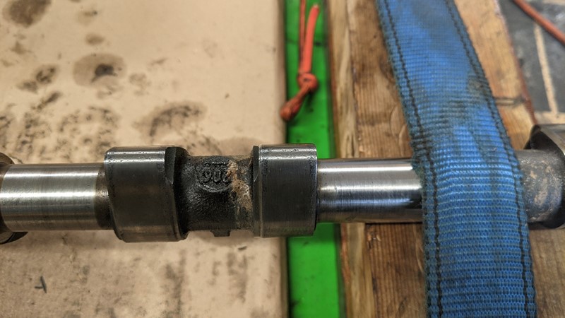
Once the camshaft bearing cap bolts came out of the ultrasonic cleaner, another surprise presented its self. One of the bolts is not like the others. And its not just the colouring, the numbers on the top are in a different font. I suspect one of the bolts has been replaced, more thank likely because it was lost. It might be one of the spare bolts I found sat on the engine!
Oil supply bars
The oil supply bars are a pretty critical part of the head. They supply oil to each of the camshaft journals and keeping them lubricated. A blockage here could cause a lot of damage to the cams. When I first took the bars off, I noticed they seemed to have pressure behind them, indicative of something being blocked in them. Blowing them out with an airline released a block of snot, who knows what else is in them!
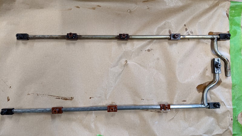
Another part to send through the ultrasonic cleaner, one end at a time. In this case, it’s done a really good job, I didn’t realise the bars were meant to be silver and not yellowed. Reassembled with some fresh 10w40 and new rubber sealing rings and everything is ready to go back together.
What’s next?
Well, hopefully, that’s all of the parts refurbished and cleaned and I can start to put the cylinder head back together. All of the part cleaning has resulted in a rather filthy garage. Before any assembly can begin, the work surfaces and tools are going to need serious scrubbing. Then the building can continue!
M
NEXT – Building the Cylinder Head
PREV – Bottom End Teardown
Back to Citroen articles
Back to Automotive articles