One of the most common questions I’m asked is will the module from Model_A fit into Model_B. Well, that’s one of those questions that creates more questions than it answers. Usually, compatibility between Model_A and Model_B is usually dependant on the electrical architecture.
In this article, we will take a broad look at what makes an electrical architecture and how they are applied to the Land Rover range.
What is an ‘Electrical Architecture’?
In it’s simplest form, electrical architecture is the structure used to arrange the module within a system. The location of every module on a network, the signals each module needs to send and receive and the priority of those signals are just a few of the elements that go into developing an electrical architecture.
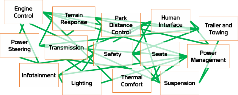
Without an architecture, the complexity of a modern car is simply impossible to manage. The graphic above gives an idea of how complicated the interactions could be. It is only a simplified example, the true complexity of a modern vehicle electrical system is mind-blowing.
Structuring an Architecture
In previous articles, we’ve seen how a Controller Area Network can help to reduce the physical wired connections between modules. Each network can only handle so many modules, or more specifically a limited number of messages. Too many messages and bus errors might start to occur or the response rate of modules will slow down.
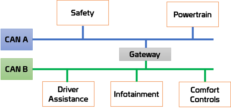
Since the early 2000’s multiple vehicle networks have been common. Back then high-speed communication modules were significantly more expensive than medium speed modules. This meant there were typically two networks where modules dependant on high-speed communication where on one bus and everything else was on a second network. The image above shows a semi typical layout.
Architectures and Message Databases
Understanding which modules are on any particular network is only part of the challenge. To ensure that a network isn’t overloaded with messages, there needs to be a list of what messages a module requires and sends. To fully define a network, the frequency of these messages also needs to be known.
A user pressing the button to lower the window and a half-second passing before the window begins to move wouldn’t be a big issue. In that same half-second if the crash sensors detected an impact at 80mph the vehicle could travel 16 metres or 3 times its length. The number of messages and how often they are sent determines the amount of load on the network.
This typically means every architecture has a different message database.
Every Increasing Complexity
My 13MY Freelander2 has around 20 modules. The 14MY Range Rover has over 50 modules. Feature and performance expectations for different models drives differing numbers of modules. And as the automotive industry develops, cars gain more and more electrical features. One of the fastest developing areas is driver assistance with everything from adaptive cruise control to lane keep assist, blind-spot monitoring and surround cameras.
The more modules required to deliver customer features, the more messages and network traffic. A new architecture often forms when a network becomes overloaded and needs to be divided or rearranged. A new platform or significant additional features can also drive a new architecture.
Land Rover Platforms

To understand commonalities between architectures, it helps to understand something about the era in which they were formed and platform they were created for. Platforms are complicated things, but here I have grouped vehicles by their intended market sector.
The Freelander2 sits in the ‘Compact SUV’ sector and uses the EUCD platform developed between Ford, Volvo and Land Rover. The D8 platform for Evoque and Discovery Sport was a modified EUCD platform.
We can also see that about the time the Freelander2 had a significant electrical architecture change (13MY) the Evoque was already out in the world, the Discovery4 had already received a significant facelift and Range Rover was just about to arrive.
Defining the Architectures
DISCLAIMER
I have to confess that what I’m going to describe next is based only on my experience working with these cars. It’s pretty much a best guess, and the newer architectures I know little about. Take it with a pinch of salt!
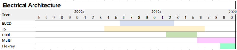
The image above shows how I personally like to break down the architectures. The colouring in the previous image of the Vehicle Timeline matches this architecture format. Until I started to compile this list I had always thought EUCD came first, but the Discovery3 was out long before the Freelander2 and used the T5 architecture.
EUCD
Ford, Volvo and Land Rover jointly developed the EUCD platform. In my limited experience, I find some of the structure and naming seems to copy what Volvo already used which would make some sense. There is also a lot of similarity between EUCD and T5. Two CAN network, a High Speed (HS) at 500k and Medium Speed (MS) at 125k, form the EUCD architecture.
T5
This is the first architecture I ever interacted with. My personal view is that this was Land Rover first ‘attempt’ at making a full CAN architecture. Certainly, architectures that followed were cleaner and somehow more organised. In my experience, I find a lot of synergies with Ford naming convention which would make sense given the era it was created. A single HS and single MS bus form this architecture.
DUAL
The DUAL CAN architecture was the first to carry the GEN2.1 infotainment. It was also the point at which the Land Rover architecture became harmonised across the product range. This is my favourite architectures as its the one I know the best. It seems to take the best of both the T5 and EUCD and make them fit for Land Rover rather than being carry over. I’ve always found it interesting that the wiring diagrams show that the L405 Range Rover carried DUAL CAN architecture for just a single year. A single HS and single MS bus form this architecture.
MULTI
The MULTI CAN architecture seems to be the same as DUAL CAN but spread across four CANbus. Given the relative complexity of the Range Rover, it isn’t a surprise that the DUAL CAN bus was simply split. It’s worth noting that in my experience modules from a medium speed MULTI CAN vehicle has the same part numbers as a DUAL CAN vehicle! Two medium-speed buses (Comfort, CO and Body, BO) and two high-speed buses (PowerTrain, PT and Chassis, CH) form this architecture.
FLEXRAY
If I’m honest, I don’t know a lot about this one. I believe the former PowerTrain CANBus becomes much faster, effectively an ethernet network. Whether this is a different communication method or something like CAN_FD I don’t know. Cars with this architecture usually have the ‘blade’ interface and the NGI infotainment system
How do we use this knowledge?
So now we know a little about the architectures, how can we use this information? Well if we want to try to add a feature from another car onto our Gen2.1 Freelander 2, we know where we might be able to get the feature from. Some Jaguar platforms share these architectures giving another opportunity for donor parts.
I would like to think that the discussion about an architectures database goes some way to explain why some modules simply can’t move between one architecture and another.
That said, without grabbing a module, plugging it in and coding for it, we can’t be sure if a module from vehicle A will fit in vehicle B.
Hopefully, this article will give you a clue if it is more or less likely to work.
M