
In a previous article, I proved out the idea of using an Arduino and CAN adapter board to get onto the Freelander’s CANBus network. To build on this, I wanted to make a CANBus adapter with dual channels. Messages could be passed between the channels, and the Arduino would be able to interrogate the messages. This CAN-in-the-middle (CITM) adapter allows real-time interaction with the messages and a whole number of opportunities
CITM Adapter Overview
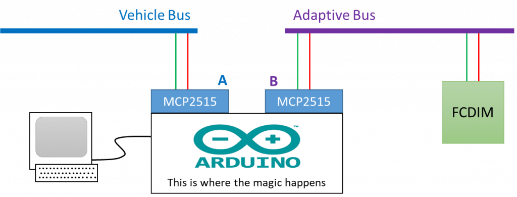
In the overview below, the existing vehicle bus is connected to one channel of the CITM, labelled as A. The messages are passed from the vehicle bus, into channel A adapter, through the Arduino and back out to the adapted bus on Channel B. Equally the flow can be reversed from the adapted bus to the vehicle bus through the Arduino.
We’ve previously looked at identifying messages sent onto a bus by a specific module, at a bench level. This process meant only one module was on the BUS so it was easy to identify which message was sent out by the module. But on a vehicle bus, there can be a number of modules and an even greater number of signals.
By placing the CITM adapter between the module under investigation and the vehicle network, it is possible to see the direction of the messages. This in turn simplifies the task of identifying which messages relate to a module, allowing the direction of the message flow to be seen.
The electrical circuit
The electrical circuit is very simple to the previous design. In this case, two TJA1050 adapter shields are connected to the Arduino. The signal wires for both CAN adapter boards are connected to the controller. Each Chip Select (CS) line is connected to a different pin on the Arduino, which allows each CAN adapter to be controlled in sequence.
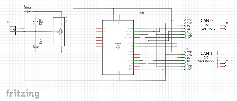
Again, the circuit was designed using the Fritzing software. The picture above shows the schematic view of the circuit. This time the parts where no positioned in the breadboard view as a slightly different approach was taken.
PCB Design
Along with the Breadboard layout and Schematic layout, Fritzing can also help with the design of the (PCB Printed Circuit Board). The software isn’t the best for detailed electronic designs, but in this case, the PCB layout was perfect for the size of the board.
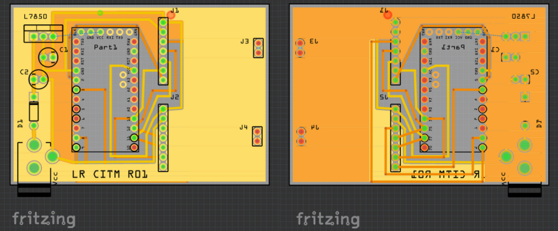
Amazingly it only took a short while to turn the schematic into a PCB outline. The first PCB design I ever made was drawn very carefully in Microsoft Paint and printed out. This process was far less stressful. Unfortunately, I seem to have forgotten everything I knew about PCB design and the resulting outlines, shown above, are terrible. Never mind.
Getting the PCB made
One of the most interesting functions of the Fritzing software is the ability to export the PCB design directly to a fabrication house. I’ve never had a PCB design professionally made before, so this was something of an adventure I wanted to take. The process was surprisingly easy and with a couple of clicks, and payment made, the order was in.
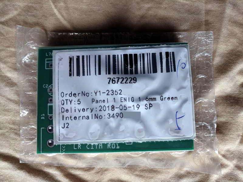
A month or so later and a small package arrived from JLC PCB having been manufactured in China. This was a surprisingly exciting arrival, far faster than had been predicted by the ordering process. I certainly didn’t wait long to unwrap them!

I’m not sure the picture does the quality of the board’s justice. They did take a little while to arrive, but the £15 or so for 5 pieces that the cost, these circuit boards are fantastic value. I definitely should have paid more attention to the PCB design before I sent it for manufacture, the faults were really obvious now they where made.
Populating the board
It didn’t take too long to populate the boards. Rather than the Arduino UNO that was used to prove the concept, this design uses an Arduino Pro Mini. The controller needs a regulated 5v and to deliver this the design uses an LM7805 regulator. This converts the vehicles 12v nominal supply voltage so something safe for the Arduino.
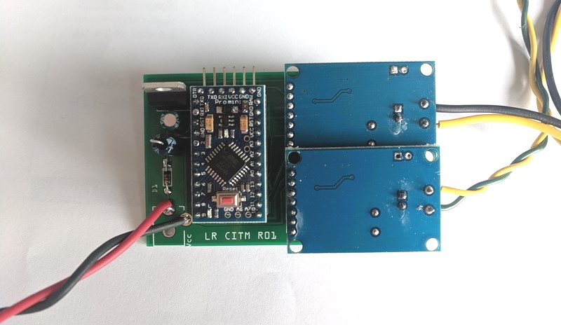
The same CANBus shields were used as the proof of concept design, however, I didn’t consider the width of the board. Or in fact, measure the boards before designing the PCB. This lead to the boards overlapping at the edges. It worked and made the board more compact, but it wasn’t intentional.
Programming the CITM
Because the Arduino Pro Mini is so small, it doesn’t include an onboard USB adapter like the UNO. Instead, a TTL to USB adapter is used to connect the board to a PC and allow it to be programmed. After that, writing the commends into the Arduino IDE is much the same as any other type of board.
Using the code from the previous project as a base, the changes to get both CAN shields working are quite small. Like in the first project, we have to initialise each CAN shield, remembering which pin of the Arduino we are connected to. In this code I have called the CAN channels CAN0 and CAN1.
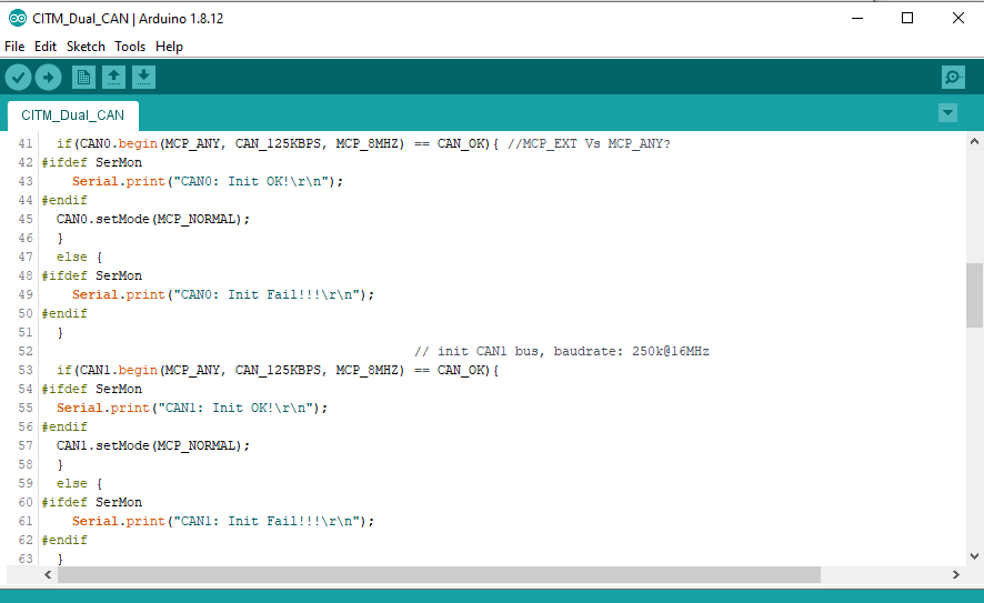
To make the pass-through work, we need to read a message from the vehicle CAN (CAN0) and send it through to (CAN1). If we send this to the serial port, we can see the direction of the messages on the connected PC. This allows us to quickly build up a picture of all the message the module is sending to the BUS. If the module was an input device, like a set of buttons, we could quickly identify which button press relates to which signal.
The code in the GitHub repository also includes some filtering to allow different signals to be modified. In this case, the CCF byte for the vehicle type can be changed in real-time. In the case of the infotainment screen, we can tell it that it’s in a different car and potentially find new features.
The source code for the project can be found on the BXProject GitHub pages here;
https://github.com/BXProject/CITM02
Real-World Application
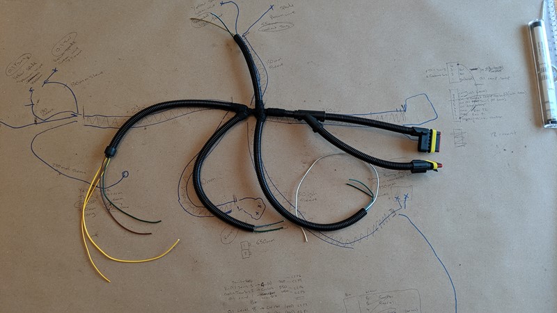
To make use of the CITM in my own car, I decided to make up a small harness. This allowed the circuit board to plug in between the infotainment screen and the vehicle harness. This way the flow of data between the vehicle CANbus and FCDIM could be monitored.
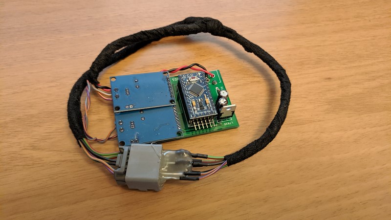
I’ll cover the application of the adapter in another article, but it did make the process of identifying signals easier. No more guessing which messages where being sent by the module. Specific outputs could be identified by pressing buttons on the screen and changing modes.
I’ve actually had use for the CITM adapter in work as well. It is used regularly to simulate specific CANBus traffic to allow certain operations in the target ECU to be checked. I hadn’t considered other uses for the adapter board during design, but it’s proven to be very handy!
I’m still impressed that the PCB design, with all its faults, worked the first time. And the process was remarkably simple. It’s proving to be very useful with all five PCBs populated and in use. While the CITM adapter board has turned out to be very compact, I’m sure the design could be improved. Perhaps by incorporating the CAN shields into my PCB? Certainly, something I can look at in the future.
M


I’ve read all your posts about CANbus, all are very interesting, especially for me the insight into finding 2nd parts and connecting to them with a captured bus play back.
Looking at your code in Github it is interesting that your commented out line for 0x400 initially read 0x0B for the model, my FL2 MY2014 SE TECH Manual has 0x08 it makes me wonder what the difference is, maybe extra / less funtions.
ID 400_01 8 01 08 02 02 01 0B 02 02
First off, apologies, the VIN is in Blk2 and has the address 0x401 (not 400 like I mentioned of FL2 forum)
Generally, the model year seems to have little or no impact on the FL2, certainly not on the multimedia components. The brand and vehicle type have a much greater impact. The model year is used by the SDD tool to identify the correct software that should be used by certain vehicles. It is quite common for hardware change to be introduced at model years which need specific software, so the CCF model year is one way to identify these. Personally, it’s not something I would change and then use SDD to update software as it will create chaos.
I’ll reply to your email now
M
M, you have a gift for communication, instruction.
Oh, wow, that is incredibly generous. Thank you Bill, that means a lot to me!
M_ , It appears that JLR may have used different CCF node IDs to “differentiate” models. My X150 uses 400 and 407. The X250 is said to use 401 and 402.
Do you know of another JLR model that may use 400 and 407? If not, maybe use your CITM as translator between the X150 and X250 parts?
Hi Bill, X150 pre-dates all of the LR electrical architectures I know. As I understand it, the X150 would have been developed by Jaguar very much under the ownership of Ford (Jaguar was bought by Ford in ’89, moved to PAG in ’99 (Land Rover joined in ’00), and JLR formed in ’07. The original XK launched in 2005, but would have been project planned during 2000/2001 before Land Rover entered PAG. In the early days of PAG (and some would say even today), Jaguar and Land Rover would have been kept very separate. So while I largely write about Land Rover in the JLR era, you pretty much have a Jaguar with origins in the FORD era. I don’t really have knowledge of pre-X250 cars, but I suspect we would need to look at other 2000 Ford-era cars to find out if other vehicles send CCF on 0x400 and 0x407. Maybe X200? or perhaps X400 and the CD132 platform?
You probably can use the CITM to map between the X152 0X407 and the X250 0X401, but I doubt there would be a direct correlation. It could take years to map out the FORD CCF structure!
Hope that helps
M