

Rather than try to talk to a module on a car, it would be wise to experiment with a module ‘on the bench’ first. We’ve previously looked at how to find the right module. In this article, we will look at making a direct CANBus connection. First, we will identify connectors, then find a wiring schematic, and finally get wired up.
To talk to any module we will need to power it with 12v and connect it to a CANBus adapter. We’ve previously covered the CANBus adapter so let’s have a quick look at power supplies.
Powering Up
For any electronic project, a basic bench power supply is always a good investment. It is possible to make one from an old PC power supply. However, a basic Chinese 0 to 30v 5A supply can be picked up for around £45 from eBay or a little less for something second hand. Eventually, you’ll need something with a bit more grunt. I would happily recommend a 40A fixed voltage Mercury power supply for automotive work.
Identifying Connectors
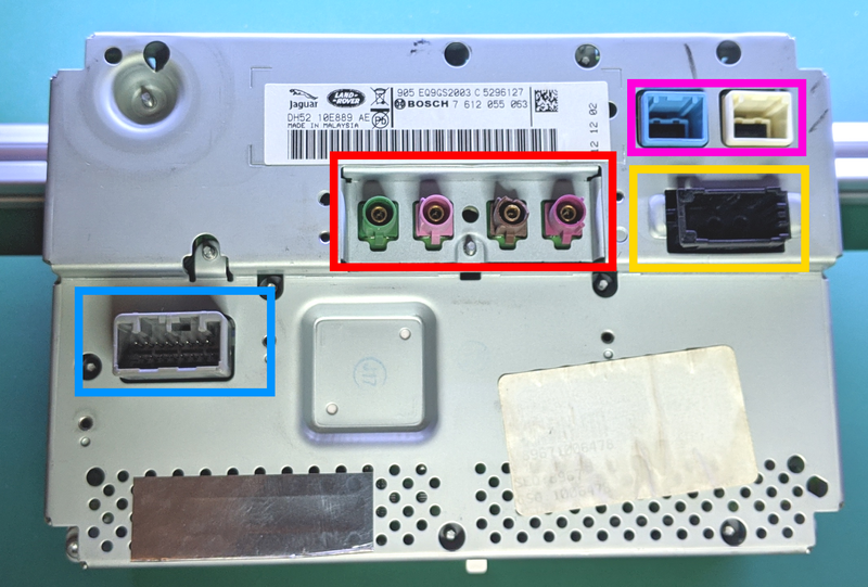
On first look at the back of the display, there are a LOT of connections! Fortunately, we don’t need connections to all of these to get talking to the screen. All of the connectors here are standard automotive types used on many cars by multiple manufacturers. By doing a little research through an electronics component supplier like DigiKey or RS it’s possible to identify the type of connector, its family and its usual purpose. I’ll share some of my own learning for this module;
- Red Box – FAKRA connectors – Used for video such as cameras
- Pink Box – LVDS connectors – Used for image data
- Yellow Box – MOST connector – Optical transmission of audio data
- Blue Box – MX34 connector – Power and bus data transmission.
As none of the other connectors are suitable for power supply, the grey connector in the blue box is the one we are really interested in. In this case, it is a 16pin MX34 family connector made by JAE. A quick Google will let you buy the housing and suitable pins. While I’m giving you a short cut here, it is possible to get some connector information from JLR through TOPIX, we’ll come to that in a moment.
Research with TOPIX
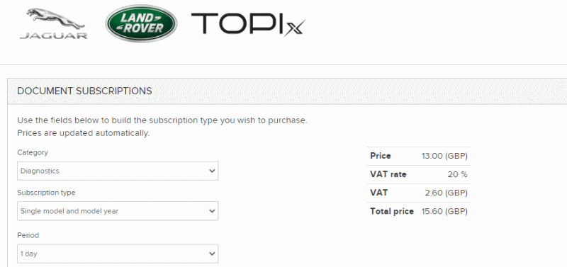
Next, we need to know which pin to wire to what, and for that, we need a wiring diagram. We have two options here, a good Google will find the “Freelander 2 2013 wiring diagram” is available online as a PDF but some times the best solution is the manufacturer. Land Rover uses a system called TOPIX to allow anyone to access technical data including the wiring diagrams and connector details for a small fee, £15.60 for a day.
Terminating Resistor
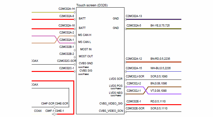
With the wiring diagram in front of us, we can make a judgement that we need two ‘Batt’ connections, the CAN connections and a ground connection (pin5). On LR wiring diagrams, the terminal has a number next to it with the connector location (C2MC02). The suffix is the connector, in this case, we want connector ‘A’ (C2MC02A). The number after the dash is the pin number, 8 and 16 for the battery connection. As we will be connecting to the CAN adapter directly, we will need a terminating resistor between the CAN HI and CAN LO wired.
This is the electrical equivalent of putting soft furnishings and carpet in a room to absorb noise. The more technical term is ‘reflection’, the idea is the same. By putting a 120 Ohm resistor across the two CAN wires noise in the network is absorbed. CAN won’t work correctly without this termination resistance. We don’t need a termination resistor when working on the car as the resistor(s) are built into the instrument cluster and the body control module.
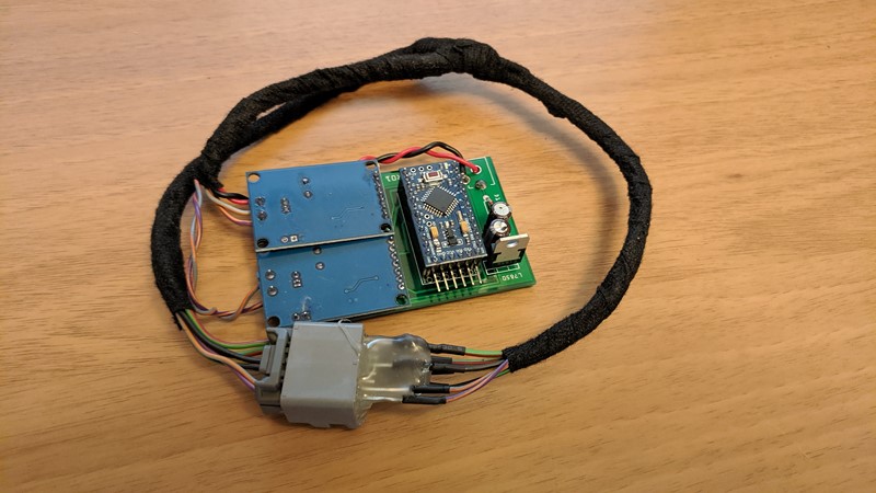
Direct CANBus connection lead
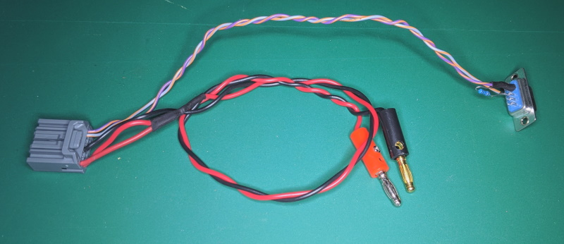
After a short time cutting and soldering wires together, we end up with a direct CANbus connection lead. You can see the termination resistor poking out of the DSUB9 connector.
Hopefully, this harness will work the first time. I’ve double-checked my pinning against the index on the connectors and the wiring diagram. I won’t test it right now, I’ll save that for another article.
M
prev: A module to play with
next:

I have a query I have a 2005 Range Rover L322 and my blue tooth module has stopped working i’m looking at installing one from a 2008 freelander 2 I know i only need four wires to make it come to life my question is which wires and what pin numbers and the location of them.I have all 32 pins on the range rover but only require 4 for the module to come to life is it do able any assistance you can provide will be most helpful.
Kind Regards
Hello Manminder,
The L322 and the pre 13MY L359 (Freelander) do not use the Gen2.1 system, and I don’t know their system too well.
Looking at the wiring diagram for a 2006 L359, Pin A1 is power, Pin A2 is ground. The DAB unit is controlled by MOST so has no CANbus connection but does need to be in the MOST ring (orange optical cables).
I hope that helps
Cheers
M