
In the CANBus article series, an industry-standard network adapter and opensource software were used to take a log from the car. That’s fine, but what if you don’t have access to a £600 piece of kit? What about building a DIY CAN Bus adapter for £12?
Where to start making an adapter?
A CANBus adapter interface needs a handful of simple components. Something to convert electrical pulses into digital data, CAN Transceiver, then something to convert the data into information, CAN Controller. The flow of information then needs somewhere to go, ideally into a PC. There are a wide variety of homemade adapters that you can read about on the internet. In this case, I want to throw something together quickly to prove to myself in can be done, before designing my own circuit board.

I have to admit to not being particularly keen on programming and like to take the easy way out where I can. For this reason, the majority of my electronics projects are based on the Arduino microcontroller. This project will be no different. Then I will be able to use standard CAN Bus interface boards, controlled by the Arduino to get information from the network.
Arduino Controller and CAN Shield
The Arduino is a simple circuit board with everything you need in it to run a simple program. It’s as easy to use as plugging in hardware modules (called shields), uploading a program (called a sketch) by USB and letting it run. There are a few different form factors of the Arduino microcontroller, offering different features. I tend to start with the original UNO and scale down to the PRO MINI or NANO.
The biggest advantages to using the Arduino is the popularity and simplicity of the code. The Arduino IDE (programming software) makes checking an uploading code very straight forward, and because of the Arduinos popularity, you seldom have to code from scratch. Just find a project that’s close to what you want and tweak the settings to match your hardware.
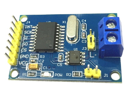
There is a near-infinite range of inputs and outputs available as Arduino compatible shields. This makes finding suitable hardware easy and quick with just a basic Google. In this case, I will use an off the shelf TJA1050 CAN Bus adapter. It comes on a small daughterboard, as above. It’s not a shield in the Arduino format, but I have a solution to that in the form of a breadboard.
Designing a circuit in Fritzing
As I mentioned before, Arduino is so popular, that you seldom have to start from scratch for any project. For this CAN Bus adapter, my inspiration has come from the @dimitarmk.com blog. This gave me some ideas on hardware to use and how to set up the Arduino but didn’t give me everything I needed.
To design a quick circuit, I like to use Fritzing. It’s a simple and cheap program which allows you to make a circuit in a number of different views. The software is highly supported by the Arduino community so most components and shields you can think of are available for it. Circuits can be drawn up in Fritzing in a number of ways. You can start by drawing up the circuit as a 2D drawing, then switch to a 3D view of components to work out how you might connect them. This is exactly how I created the first design. Later this can be expanded into PCB design.

Assembling the CAN Bus Adapter
I had planned to build on a breadboard, but the circuit was so simple I went straight to perf board. The Fritzing design work meant I had an easy to follow the schematic and could assemble the parts together. The picture below shows just how simple the wiring really was!
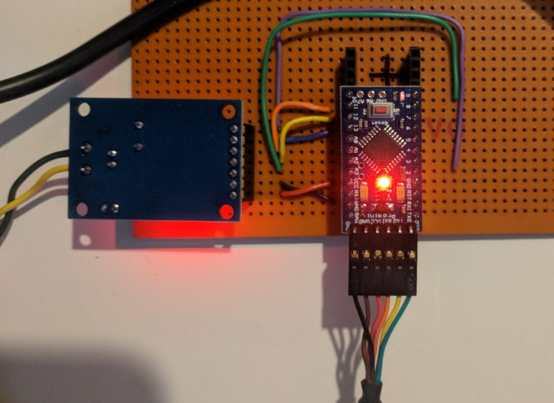
Colourful and straightforward wiring makes for easier assembly. The Arduino PRO MINI could then be programmed using a TTL to USB adapter plugged into the PC. This makes the Arduino board appear as a serial COMM port on the host computer. The Arduino integrated development environment (IDE) software can them program and transfer data through this data connection.
Writing the code
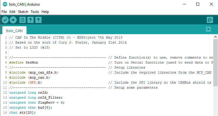
The IDE makes writing code for the Arduino simple and quick. It’s a slick piece of software including everything you need to get the HW programmed. The programming window helps by identifying common commands and colouring them as you type. It also checks as you type to give you some idea of small errors. The compiler then checks the whole program for errors and tries to tell you where the problems are. These days the IDE can automatically grab the libraries you need to make your code work.
Rather than try to write a hardware interface program from scratch, many people who use the Arduino share their code. So I can use a prewritten library and adapt an example program to my needs. For me, I find the availability of example code and libraries to be the biggest benefit of using Arduino.
In this case, I’m using code from Cory J Fowler who has a pretty good interface library and handy examples. The source code was written for different hardware, so I have to change a few settings to match. I try to put plenty of comments into my code, as I never know when I’ll get it finished. Coming back to a program later and trying to decode your own code is awful.
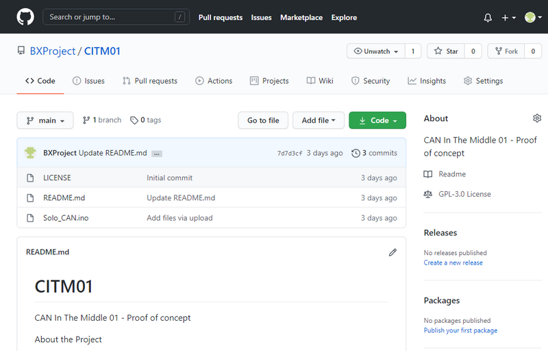
And of course, to make the Arduino community work, I need to share back the code. My preference is to use GitHub. The source files for the ‘Can In The Middle’ project version 01 can be found here;
https://github.com/BXProject/CITM01
Testing the hardware
So with the hardware assembled and the Arduino programmed, it’s time to see if it works. I’m not confident enough at this point to just connect it to a car. Instead, I’m going to use BusMaster to play out a log file on to a short CAN Bus. I’ll then connect the FCDIM (display screen) to the BUS so I know it’s working. The basic topology of this layout is below.

The first time I tried to make this work, I missed the pull down resister. The resistance between high and low wires should be about 60K Ohm. I use a couple of parallel 120K Ohm resistors. There should be one at either end of the CANBus wires, but in this case, the network is so short I put them in together. Then the moment of truth, turn everything on an press play in BusMaster.
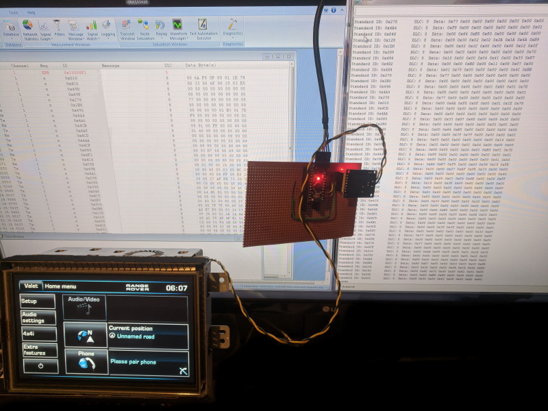
IT WORKS!
The poor quality image above shows the BusMaster playback on the left and the screen alive and working on the lower left. In the middle the working adapter hardware with power and data lights. And on the right, the serial monitor window in Arduino shows the recorded data.
DIY CAN Bus adapter concept proven?
As a proof on concept, this has worked pretty well. A project is always more enjoyable when it goes smoothly, and I certainly have a solid base to build upon. I noticed when comparing with the BusMaster log file, there is an occasional timing difference with the serial data. I’ll have to look at this in the future to see if it creates a problem.
The next step will be to see if I can put a DIY CAN bus adatper between the ‘netowrk’ and the screen. In this way I will be able to interact with the flow of data, and, hopefully, change it in real-time. I’ve already started the second version on the ‘CITM’ so hopefully, I’ll have a follow-up article soon.
M


Hi, How did you connect with the BUS Master software. I mean which driver selection you have selected to setup the communication.
Hi Abhinav, when I used BUS Master, I was attached to a Vector Dongle, so I used the Vector Drivers. However, more recently i have been using the USB/CAN adapter from Innomaker which has been an excellent purchase. I currently have one in a live environment connected to a RiPi4 logging a vehicle CANBus.
I hope that helps
M