Now that we understand what a communications bus is, why it’s used and what it looks like electrically, it’s useful to know how information is transmitted. Although we’ve used an adapter and connected to a network and seen some signals, it’s useful to understand how the electrical signals turn into CANBus data frames?
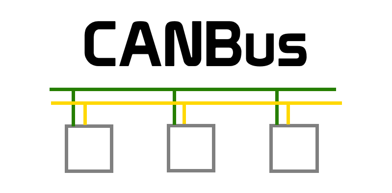
CAN Bus flow
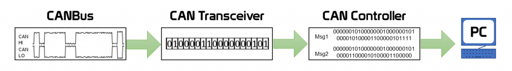
We have previously seen how the raw electrical signals on the CANbus are converted to data by the CAN Transceiver. We then touched on how the CAN controller breaks up the constant flow of ‘0s’ and ‘1s’ into the individual frames. The image above shows the flow of information.
Breakdown of a frame
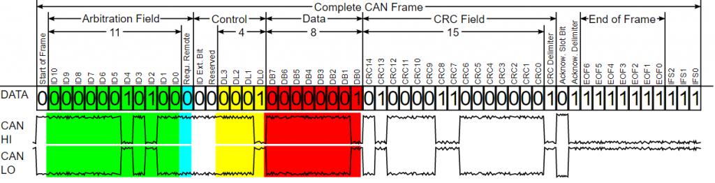
CANBus data frames have a number of components to them, as shown in the image above. The “CAN 2.0a Specification” documents detail the structure of a CAN frame in great lengths, far beyond what we really need to know. The important parts are coloured. The green section is the address of the CAN Module (ECU) which put the message on the CANBus. The length of the data that is being sent is shown in yellow. The red section is the data that the CAN Module is sharing with all other modules on the CANBus.
Frames in BusMaster
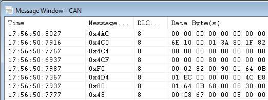
The frame data is easier to see in BusMaster. The ‘Message Address’ is ECU that sent the message. ‘DLC’ is the number of bytes in the message, and the ‘Data Bytes’ show the data sent in HEX format.
Using the data
Now we can see the data, but how do we make use of it? The first thing we need to know is the modules related to each message address. We can initially apply some logic to the rate and order the messages that appear on the CANBus to get a feel for the priority of the information.
- ECU’s often transmit data from a number of addresses, so it is not a simple as identifying one message address for each ECU.
- The address of a module determines the priority on the BUS. Higher priority ECUs have a lower address value. This is how one ECU assumes priority over another. A lower addressed module pulls the BUS to the ‘0’ position for longer and in doing so stops other modules from transmitting. For example, 0x004 is higher priority message than 0x040.
- The rate at which a module repeats its message, determined from the time stamp, can give some indication of the type of module. Long gaps between messages suggest they aren’t user-driven. It would be quite annoying if you press a button and have to wait for several sends for a response!
So how do we pair addresses to a module? I have some tricks for that, which I’ll share in a future article.
M
prev: CANBus – How to crash reset
next: A module to play with?