

Following on from the well-received Sphere Table post a few months ago, I thought it about time I shared how I test sphere pressures. When I started writing this article, I quickly discovered I’d told this tale in 2014 on the now-closed BXProject Forum. However, the writing quality could have been better, and the process was full of gaps, so let me try retelling the Sphere Tester story.
The Overview
Around 2013, I visited a friend and saw their homemade sphere tester. Not unsurprisingly, I was somewhat inspired! After a year of collecting parts, I could finally knock up a sphere tester of my own. My motivation was partly to learn new skills and partly to aid my forthcoming project(s).
Still, to this day, I’ve yet to find a good guide to building your own. However, having seen one in the flesh and read up on the French Car Forum and the XM Forum (mostly about rigs made by DieselMan and CitroJim), I reckon I can make up my own!
The Parts Needed
Before building can commence, we’ll first need some parts. On top of the usual hand tools, a pail of LHM and some fluid hoses, these are the main parts you need to build a sphere tester.
A Hydraulic Pump
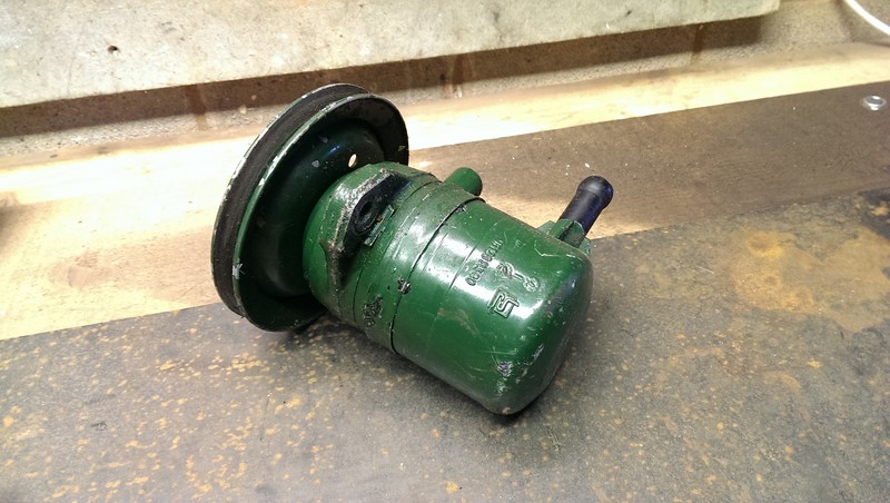
To generate some fluid pressure, we will need a hydraulic pump. For the sake of ease, I’m sticking with Citroen hydraulic parts, although there are other ways of generating pressure. The genuine pressure test kit uses a modified hydraulic bottle jack. For my build, I’m using a single output pump from a BX, I think, a 1.6 model. I found it cheap at a CCC Stratford Rally (those were the days). A dual-output Xantia pump would work with one side blocked off.
Hydraulic Pressure Regulator
To balance the supplied hydraulic pressure with the gas pressure in the sphere, the system needs a pressure regulation valve. This is where the magic happens! There are at least two different types of pressure regulators that I’ve found. I’ll return to the types and which one you need (and why) later.
High-Pressure Link Pipe
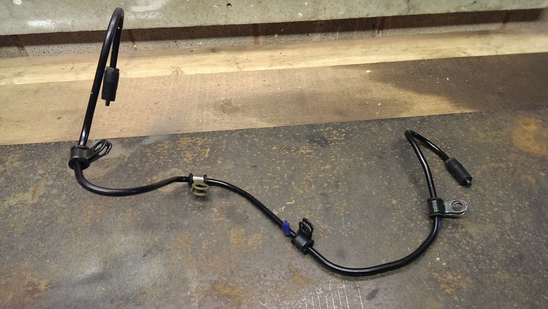
We will also need to connect the high-pressure pump to the pressure regulation valve. When building the sphere tester, I didn’t have the die for flaring a 6.35mm pipe to connect the pump and the regulator. The solution, in this case, was a genuine Citroen pipe bought from eBay for a couple of quid. From distant memory, it may have been for a 1.4 TU-engined BX. I suggest it might be better to buy a cupronickel one from Pleides. That way, you can specify the length and get a pipe that will be easier to bend.
A Suitable Pressure Gauge
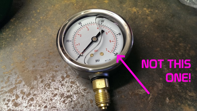
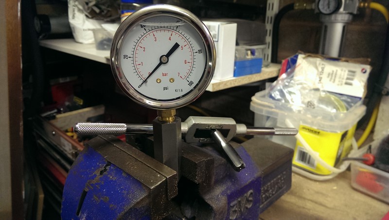
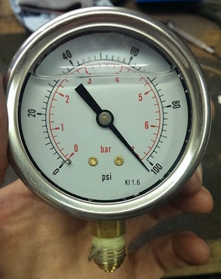
The most critical part of the sphere tester is the pressure gauge. For a sphere tester, we need a minimum 0 to 100 BAR gauge as most BX spheres are around the 65 BAR mark. If you want to check the system pressure on the car as well, then you’ll need up to 200 BAR.
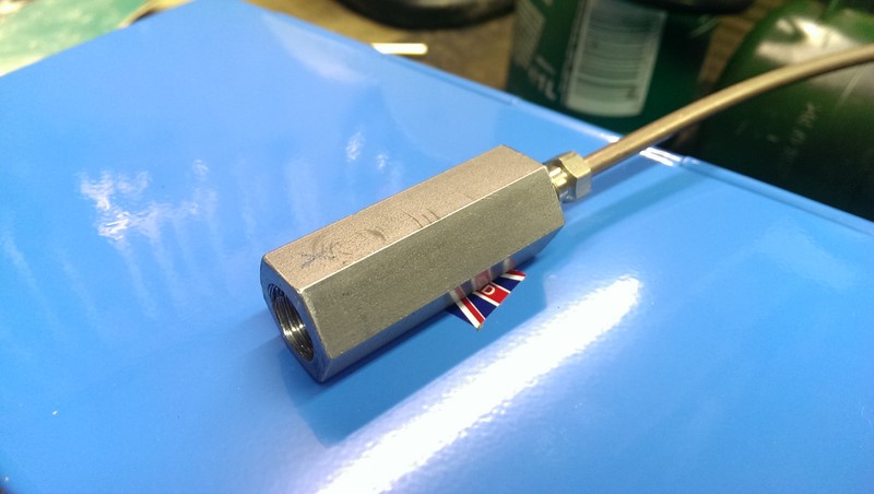
The gauge shown above is a fancy liquid (glycerine) filled type that will dampen pressure pulses. Pressure spikes are unlikely to happen in a sphere tester, but the fancy glycerin gauge was only £11 delivered from Southern Temperature Sensors, so I went for the plush one.
Suitable adapter for the gauge
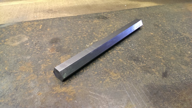
To connect a standard fitment gauge to the Citroen pipe flare, an adapter will need to be made up. We will need to connect the Citroen 3.5mm pipe flare to the 1/4″ BSPT gauge thread. To do this, I invested in suitable drills and taps and bought a piece of 3/4″ mild steel hex bar. Other methods of joining two threads are available, but this method was well within my skill set.
Fluid Reservoir and Pipes
The sphere tester will need to push some fluid around to build pressure against the sphere’s diaphragm. In the making of my sphere tester, I used a few different reservoir types. I started with a 500ml glass jar, which simply wasn’t enough volume. Eventually, I settled for an old plastic peanut butter tub at 700ml. The extra volume was just enough to get a head of pressure built up.
Generally, any container will do. I couldn’t bring myself to drill holes in the Total LHM+ bottle at the time, and opted for the generic peanut butter tub. I’d like one of the old metal LHM containers for aesthetics. But as we will see, there are a fair number of pipes that need to go into the reservoir, so get something easy to drill holes in!
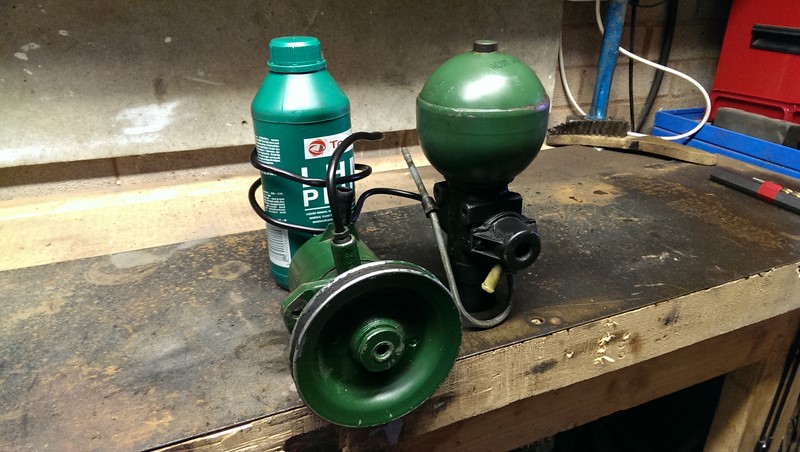
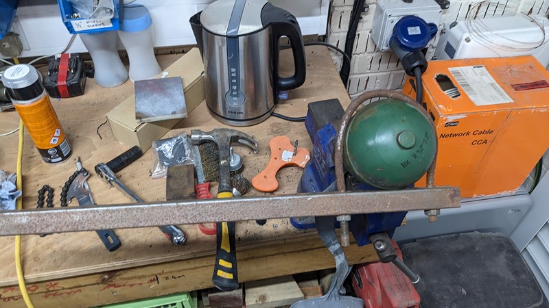
Parts Collection
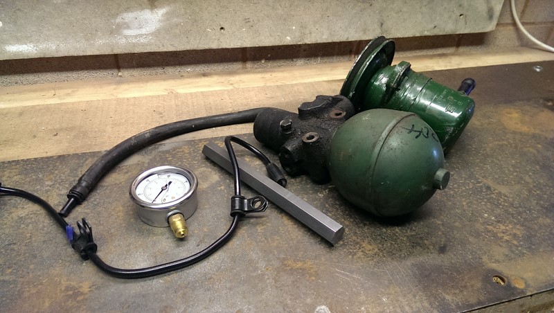
And that’s the pile of parts. We will need to add a length of 4.5mm flared hydraulic pipe, some return hoses and a fluid reservoir. At some point, it would be wise to have it all bolted together, so a frame for it all to sit on will be needed. I opted to assemble the parts to give me an idea of the size of the base required before fixing everything together.
A Note On Pressure Regulators
I learnt from CitroJim that on opening the pressure release screw (to drop the pressure), the built-up pressure in the sphere is usually dumped through the hydraulic system and not through the low-pressure return.
If we plumb a gauge onto the feed for the hydraulic system, we can’t release the pressure!
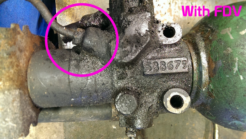
On a BX, the pressure is released through the FDV and that great big flexible rubber hose at the front of the car. This means there is a drilled and tapped boss on the bottom of the pressure regulator, which takes any excess pressure away.
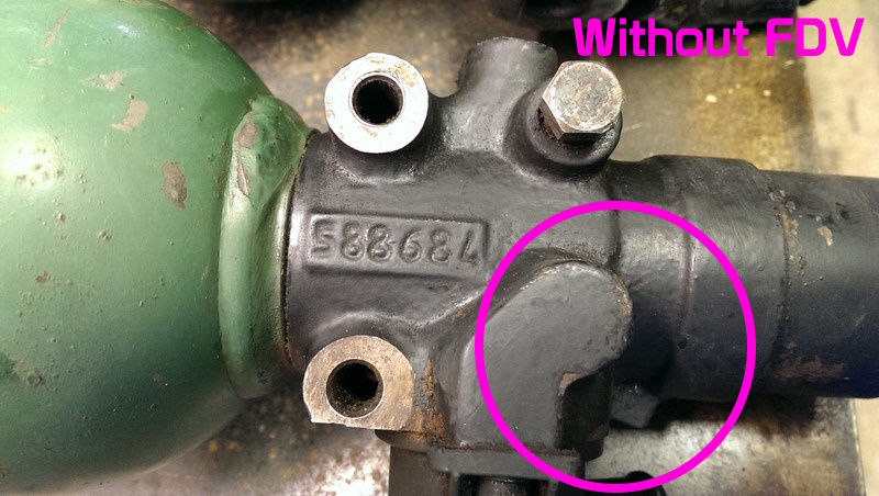
However, on later Citroens that don’t use an FDV, such as the later Xantia, this outlet doesn’t exist! This is because the later Xantia has a pump with two outlets where one port is connected directly to the steering rack, and the other to the suspension and brakes through the priority valve. This means an FDV is not required.
This means on a PR fitted to a car with an FDV there is an additional port which, handily, is opened with the release screw, so we can dump the pressure through this outlet!
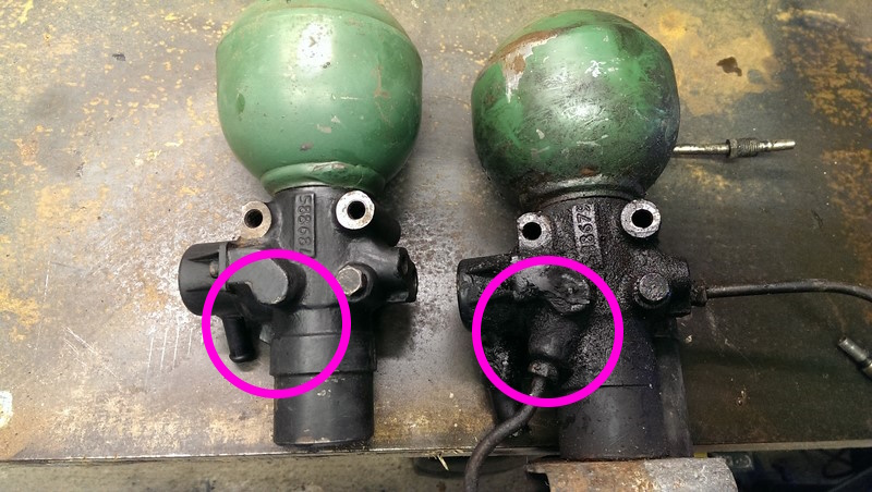
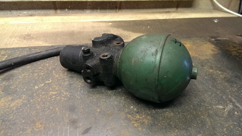
In the picture above, you can see the non-FDV PRV on the left, and FDV PRV with the extra pipe outlet (shown here with the flexi pipe attached). There are numbers stamped onto the PRs, 588684 on the left and 588679 on the right.
While it is not impossible to use the Xantia-style PRV, life is much simpler if we start from BX parts.
Making The Gauge Adapter
An adapter is needed to support the gauge and connect it to the high-pressure feed from the pressure regulator. In this case, I’m using a piece of solid mild steel ordered from eBay.
Having done my research and ordered up a couple of taps and die sets, holes were soon machined up in a 50mm length of the hex bar and drilled and tapped appropriately. A 5mm hole through the length, then a 1/4 BSPT (19) thread in one end (10mm deep) and an M9 x1.25 thread in the other (16mm deep).
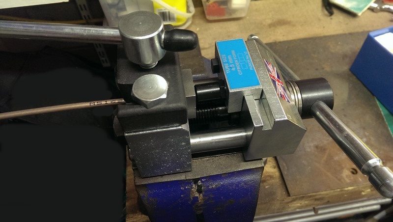
Of course, to connect the pressure regulator to the gauge, I need a length of pipe with Citroen flares on each end. In the picture above, I’m using a flaring tool bought from AB Tools. There are several pipe-flaring tool variants. However, this type has a vast range of flares available. And best still, AB Tools stock them all!
An hour, ish, of drilling and tapping later, the adapter is made up with the gauge and high-pressure pipe connected. I do enjoy running a new thread into raw steel. There is something very satisfying about creating meaningful swarf.
For reference, threads on Citroen hydraulic unions are as follows;
- 3.5 = M8 X 1.25
- 4.5 = M9 X 1.25 (Metric course)
- Old 6.35 style M12 X 1.25
- New 6mm (xantia pump) M12 X 1
Just in case you should ever need them!
A thought about pressures
The first time I assembled the sphere tester, things didn’t go as well as I had hoped. I started building pressure by turning the HP pump by hand with the PR screw closed. Within two turns, disaster. The pressure gauge went clean past 62 and all the way up to 100. I stopped turning the pump, released the pressure and tried again. Same thing, only this time, the pressure level didn’t drop!
Oh. Balls. I assumed some dirt had gotten into the gauge. Running air pressure into the gauge and pulling a vacuum didn’t help the stuck needle. Oh well. Proven the concept a bit. However, I was a bit annoyed that the gauge failed so quickly. I had expected the gauge’s untimely end would come from a rapid coming together with the garage floor.
Eventually, I realised when looking at the top of the sphere stamped 65 BAR while holding a 100psi guage what the problem might be. One BAR is approximately 14.5 PSI. Oh dear, oh dear.
Annoyingly, before ordering, I checked the X-series sphere list to see what the highest pressure a sphere gets, and checked the maximum output pressure of the pump under normal conditions (140 to 170 bar) and still ordered the wrong one.
Worse still is that the charming people at Southern Temperature Sensors even sent me a replacement gratis. I did go back to them and confess my stupidity, and asked to pay for the new gauge, but they wouldn’t have it. Very nice people. Nearly ten years later, the company seems to have wound up, so I can’t even link you to them!
First Successful Usage
Well, I got some alternative gauges very quickly and tried again. One rotation of the HP pump got me to about 20BAR, then another rotation to 30 BAR. After that, there was no more pressure increase. The pressure regulator opened internally once the applied fluid pressure and the gas pressure were equalised.
I knew this accumulator was a little flat. I didn’t realise just how flat! Only 32 BAR of an original 60 BAR. But as a first test, I’m happy I proved the system works. I can’t confess I understand quite how the pressure equalisation gives the gas pressure, but I have put new spheres on the tester and got a reading that matched the sphere rating.
The biggest issue I had with this setup was getting the pump primed. The plastic bottle reservoir and the high feed pipe made getting only fluid to the pump intake a little tricky. But a little experimentation found a balance. We’ll come to the final setup shortly.
Sphere Tester Usage
On a good day, testing sphere pressures takes just a few minutes. Although a lot of the process is dependent on how easily the spheres come off!
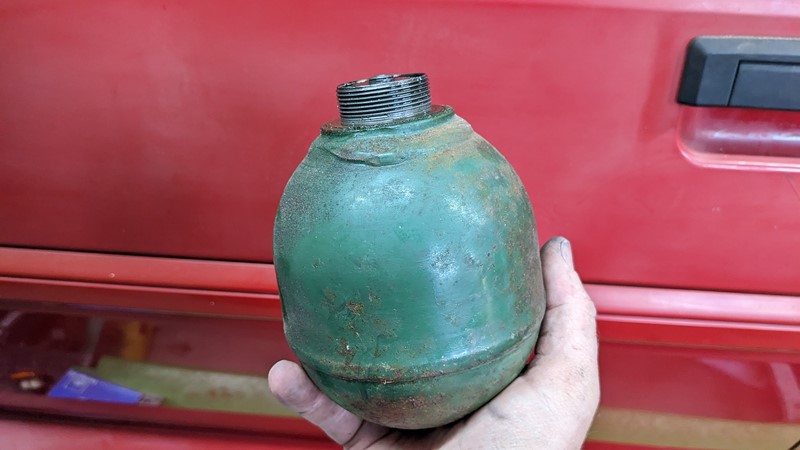
Getting the old sphere removed
The spheres on the XPO project car are looking rather tired. Given there has been no fluid pressure against the diaphragm since 2008 or earlier, the gas pressure has likely escaped through the diaphragm membrane. Time to get them off and tested.
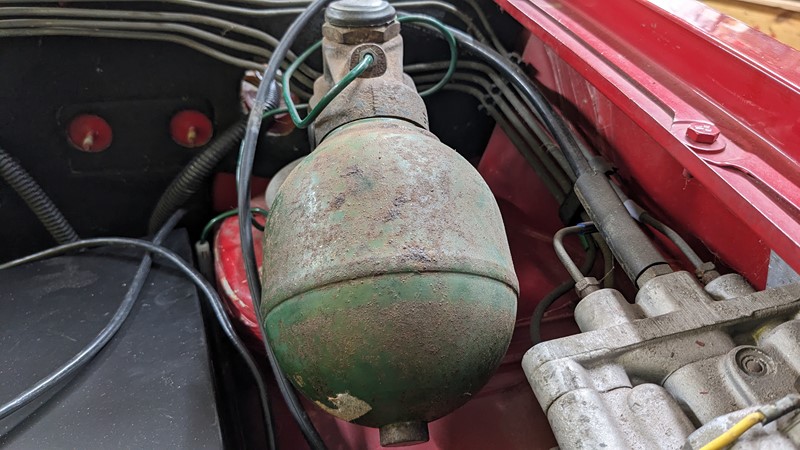
The first step is to remove the sphere, something that can be a little tricky. There is a vast range of tools and techniques available. Fancy screw-on tools and cold chisels all work, although I have something slightly more straightforward.
While my special tool isn’t pretty and scratches the hell out of the spheres, I’m yet to find a sphere it could not remove! The core of my sphere remover is a length of 3mm wall 1/2″ box section. A couple of 8mm holes where drilled through slightly closer than the width of the sphere. A length of 8mm threaded bar was then bent over an old sphere to make a ‘U’ bend and shoved through the holes.
The U-bend is placed over the sphere, nuts tightened up, and a suitable turning moment applied. And this time, the scratches are only on one side, so I can carefully hide them in the picture above.
Using the Sphere Tester
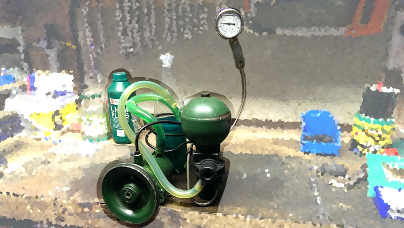
With the old sphere off the car, any remaining fluid is poured out. A small amount of contamination is bound to get into the sphere tester reservoir. However, I find it good practice to pour away the worst of any old fluid.
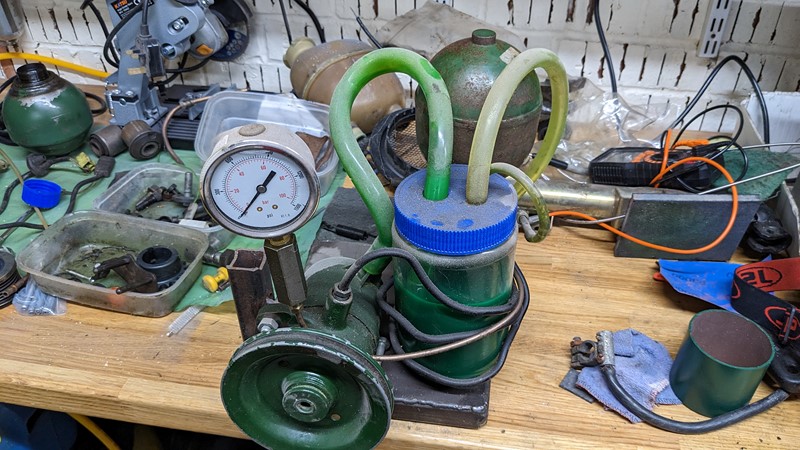
The old sphere is then screwed into the top of the sphere tester. In the picture above, you’ll see the system has a solid base, the pump is bolted down, and the peanut butter tub reservoir is in place.
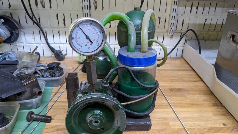
Once the sphere is mounted, the valve on the PRV is closed, and the HP pulley wheel is turned. Within a few turns, the gauge pressure rises. A few more turns and the pressure levels out at the spheres residual pressure. In this case, 40 BAR.
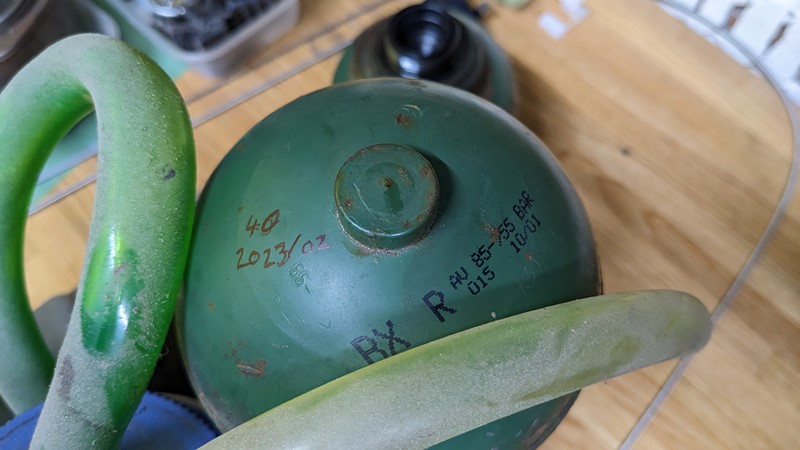
The final step of using the sphere tester is to note the recorded pressure on the sphere. A fine Sharpie usually does the trick for me. In this case, the 55BAR sphere has 40BAR left. A date always helps, so I know when the sphere was last tested.
Why build a sphere tester anyway?
Some of my motivation for building sphere tester was simply because I enjoy the challenge of building. I’m a Citroen car part hoarder, so several spheres are knocking about in the garage of an unknown state, so I have an ‘immediate’ need.
Not so long ago, a particular brand of spheres was often delivered with no pressure. Dead on arrival was a common sphere complaint, which is less frequent nowadays. As a result, I like to test any sphere before putting them on the car. And right now, I have three BXs, a total of 15 spheres. I prefer to keep good spheres on the car if I know they’re good.
In case you need them, below are some links to other builds and guides (mostly from CitroJim)
http://www.frenchcarforum.co.uk/forum/v … =3&t=36165
http://www.club-xm.co.uk/forum/viewtopi … 4f511baeed
http://www.club-xm.co.uk/forum/viewtopic.php?f=7&t=3978
Will you build your own?
I hope this brief guide has encouraged those with LHM in the blood to have a go at building their own sphere tester. For me, it was a very simple and satisfying process, and it proved to be really useful in reducing my pile of dead spheres!
M
NEXT –
PREV – All About Spheres
[…] NEXT – Sphere Tester PREV – Heater Tap Overhaul – Part 4 […]
Excellent guide. I’ll bring mine to you when they need doing ; )
Any time Panky, any time at all!