
With the suspension turret welding complete and looking and feeling solid, the scuttle repair can carry on. But, remembering that this is only a warm-up to the main event of welding in an A-pillar, there is still a lot to go wrong. From warping to blowing through and chasing holes, welding up the scuttle may not be straightforward. And as we’re about to find, there is a curveball to overcome!
Picking up from the suspension turret repair
In the previous article (and I’m starting to wish I’d numbered them), I removed the rotten scuttle panel and found rust in the suspension turret panel. This panel is pretty thick for a car, so the small patch repair was simple and easy to weld up. But, as is often the way, the cleaning up took far longer than the actual welding.
As soon as the welds have been ground down, I generally find it’s good form and a good time saver to prime the exposed and cleaned metalwork. In this case, I know I will be spot welding or seam welding into this exposed metal, so I have to make a suitable choice of primer. In this case, I’m using an etching weld through primer from uPol. Where surfaces overlap, I will struggle to get paint and topcoat in. This means I need to consider how I will seal the area off from moisture when I finish welding.
The areas of exposed metal get a good covering of the zinc-based weld through primer. There is some consideration required here. Too much primer will cause welds to become overly contaminated and potentially porous. On the other hand, I don’t want to have to strip it all out again before I’ve finished the car. Long term, the exposed surfaces will get five to seven layers of paint and some seam sealer to hopefully keep everything free from oxidisation, at least for the next 30 years.
CAD scuttle repair templates
With the scuttle area primed and ready for welding, I can begin making up the repair panel. This is a complicated piece with multiple bends in opposing directions, but I have a few time-honoured tricks to help me along. To aid in making up the repair panel, I can use the matching piece of the repair panel body cut.
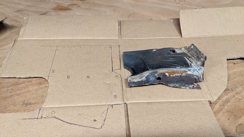
I’m using a technical technique called CAD. Cardboard Aided Design is a time-served method of making up small repair panels. The outline of the donor panel is drawn out onto a thin but stiff piece of cardboard. Any metal missing from the donor panel can be drawn onto the card, and the outline extended to match the metal cut out of XPO.
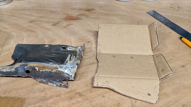
A sharp knife is then used to cut out the template, and viola, the repair panel. After years of practice, I’m getting much better at this CAD thing. There are a few tricks, though. Choosing cardboard with the right stiffness is critical. A cereal box is absolutely the best. If you’re using corrugated cardboard, consider how the corrugations will impact the bends. And of course, it’s cardboard, so make plenty of notes!
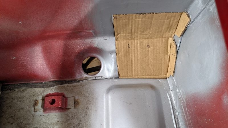
The first fit of the template is pretty good. Once offered up, I’ll note where anything is loose-fitting. Anywhere the CAD is too tight will be trimmed. Relevant places for existing or additional spot welds are marked, along with the bend points. I’ve had more than one occasion where I’ve had to throw the whole thing away and start again, usually because of rushing.
And, of course, it’s essential to check all areas of the template where it should contact. A little pressure on the card may help to check whether the lengths are right. Here the lowest seam and the card don’t seem to align, but they do once pushed together.
Metal bashing a repair panel for welding into the scuttle
With a good CAD template modelled, I can draw the outline onto new steel. It’s important to consider how you trace the cardboard. Draw the outline wide, and you’ll have a lot of extra metal trimming to do. Once the metal has been bent and drilled, it will become much harder to trim the metal.
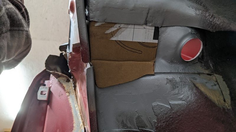
After much panel bashing, hammer-wielding and vice bending later, the metal repair panel is offered up to the scuttle, and it’s a pretty good fit. But I must confess that it wasn’t as simple as these few pictures make out. The bottom of the scuttle is not the same shape as the previously repaired suspension turret panel. Getting the panel to align this well has taken quite a bit of work, but there will be gaps. These gaps are more than likely why the factory has so much sealant here.
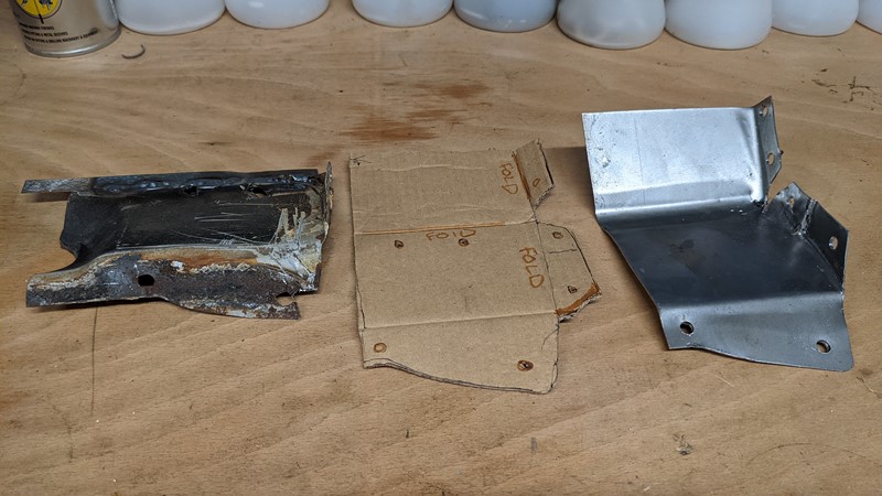
And that’s the three steps to making this panel for welding into the scuttle. Trace the donor part onto the cardboard. Trace that onto the new steel. Cut it out and bash it into place. With this repair panel being quite complicated, it’s no real surprise to find it’s taken four hours to get to this point.
Welding in the scuttle repair panel
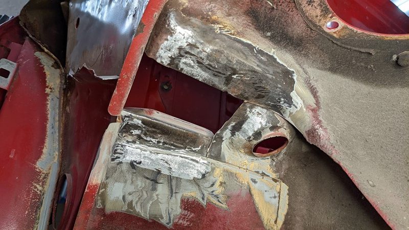
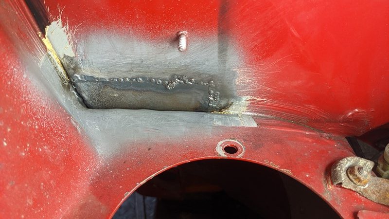
Finally, I can start to weld the panel into the scuttle. In places where the repair piece is touching a cut edge of the scuttle, it needs to be continuously welded along the whole joint. This is a legal requirement in the UK and a sensible one at that. Surfaces of the repair panel that won’t be accessible once welded get a coat of weld through etch primer.
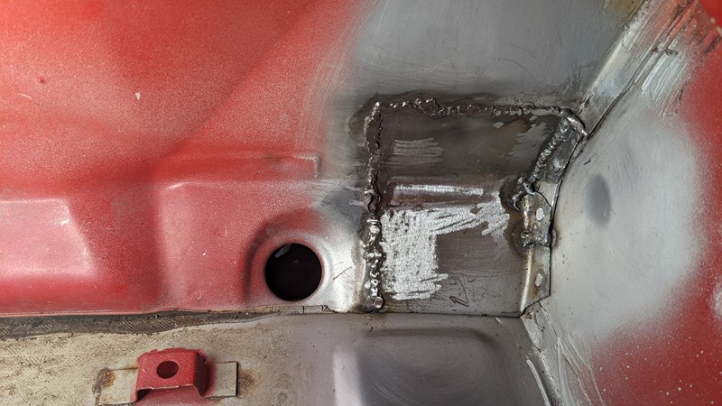
Despite my previous ‘practise’ welding, I clearly need a little more practice. That said, this welding is inside the scuttle, making access a little tricky. However, it’s good and solid and will be much neater once ground back, sealed and painted.
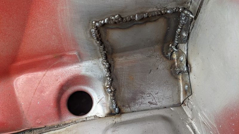
While the welding might not look pretty on the scuttle side, looking in from the engine bay, it has plenty of penetration. Given how the scuttle side looked, I’m pretty chuffed with the result. This is without any grinding, so just about perfect penetration.
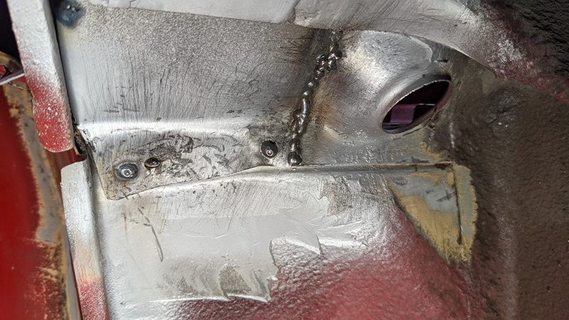
The underside gets a once-over as the penetration is slightly light here. The weld from the top side is solid enough, so this is simply belt and braces. The left-most plug weld, replacing the original spot weld, didn’t take. The weld pooled up on the lower plate but didn’t penetrate through to the other panel. There was a reason, though!
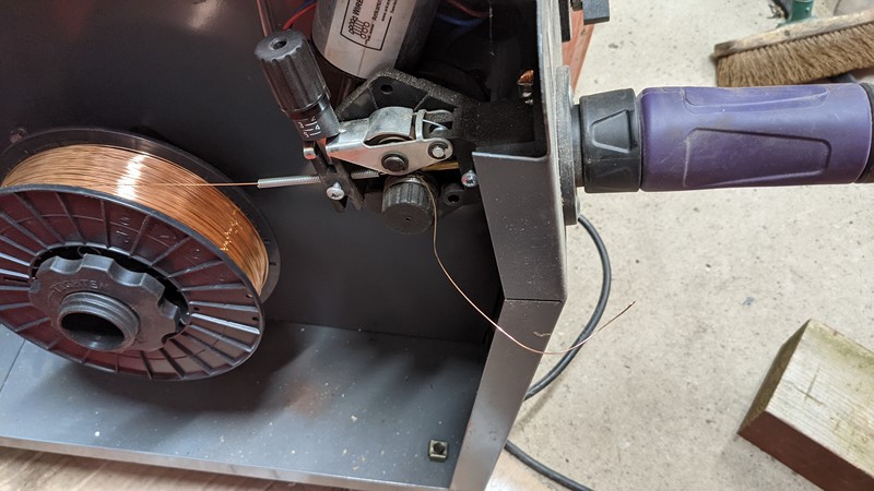
It seems the welding wire has jammed somewhere in the torch. The rollers in the Portamig 215 have kept good tension on the MIG wire until something has given in! The wire is quickly run back through the torch, allowing welding to continue, phew. It also turns out the nib in the torch has worked free, possibly causing the problem in the first place.
Flatting back and finishing off
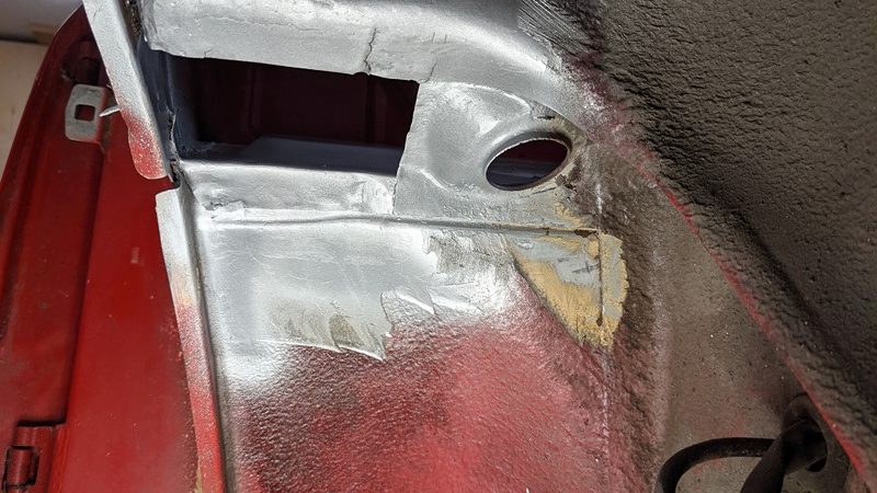
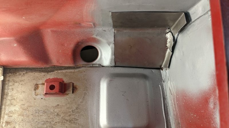
With the plate fully welded, it’s time for a bit of a tidy-up. I’m always cautious when grinding back to make a joint flush. Go too fast, and the join can overheat and fail. Take too much material off, and the joint becomes brittle and fails. So the order of business is slowly and gently.
The scuttle is a damn tight place for the grinder with a flap disc on it. I can knock down the highest spots, but I need something a little more precise to get up close and personal. So, in the end, I ended up buying a Sealey SBS260 finger sander. It’s cheap and low-power, but it works really well.
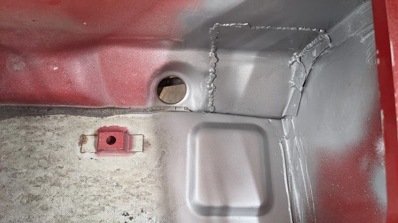
The new scuttle piece gets a few coats of etch primer once the welded seem has been sufficiently flattened off. The welded seams will all get a covering of thick sealant, which will cover the worse of the remaining protruding weld. As this area will be visible, I might take them back a little further. This might also help to stop water pooling.
What’s next?
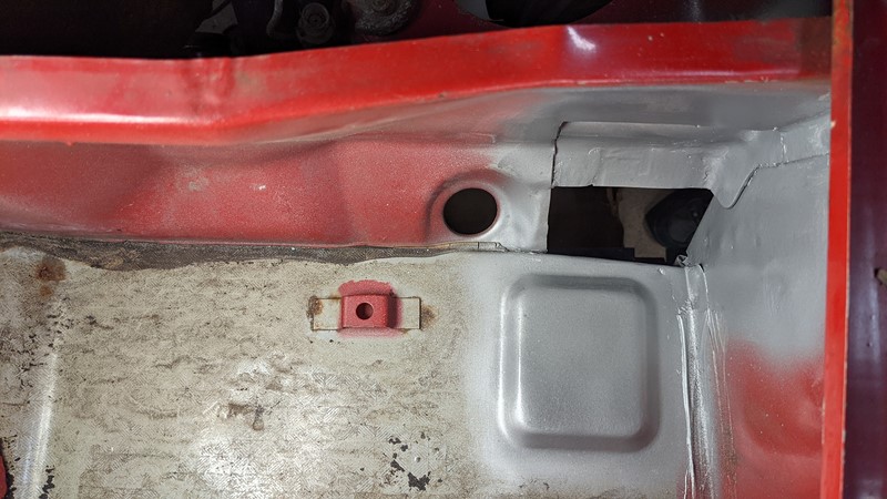
This is just the first panel I need to weld into the scuttle. The next one is a little different as there is no donor panel to copy, but it’s a much easier shape. I’m still behind my schedule, but finally, getting some metal back onto the car is incredibly satisfying. Now that I finally see holes patched up, it gives a great motivation boost!
M
NEXT – Welding the scuttle Part 2
PREV – Welding the suspension turret
More XPO Articles
Back to Citroen articles
Back to Automotive articles