
In the previous Ford 7610 Tractor article, the Trima loader was installed onto the tractor. What an adventure into ways to cause injury to yourself that turned out to be. Although, to be clear, no damage was actually sustained, just plenty of potential. Moving on, the loader was initially plumbed directly to the spool valves at the back of the tractor.
The spools are cabin lever-operated hydraulic feed and return. Unfortunately, this meant that to operate the loader, both spool levers and loader joystick had to be operated simultaneously. The resulting calamity was akin to playing two guitars simultaneously, grotesque and nearly impossible. The solution was a free-flow return.
What is a Free Flow Return anyway?
The tractor loader is a collection of dual-action hydraulic cylinders. These move in and out to make the loader arms move up and down. To move a ram in one direction, hydraulic pressure is applied to one side of the piston, pushing the ram and displacing any fluid from the other side.
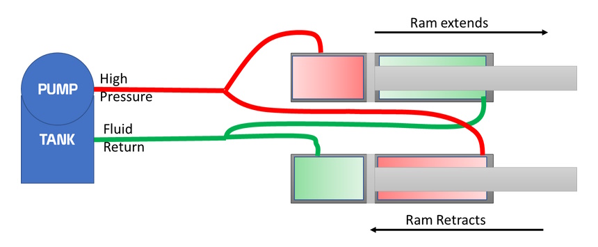
To move the ram in the opposite direction, fluid flow is reversed, and pressure is applied to the other side of the piston. This causes the ram to retract. All pretty simple, especially with this beautiful mickey mouse drawing above. However, the real world is slightly more complex.
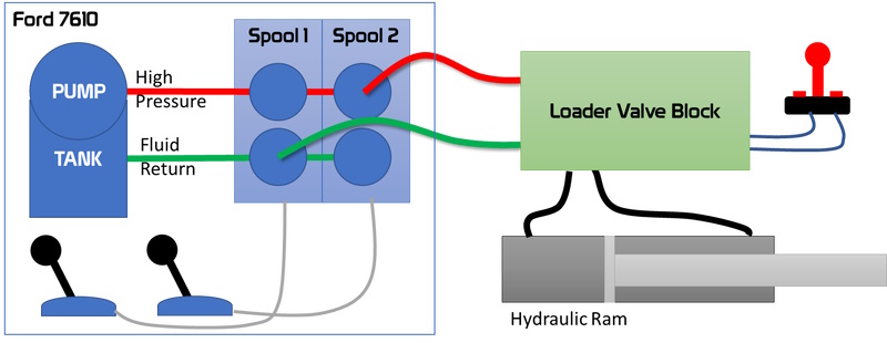
I’ve tried to describe the current setup a few times with just words, but they didn’t cut the mustard, so hopefully, the drawing above will help. The image shows the problem to be solved. The loader valve block takes care of sending the fluid to and from the correct cylinder from the cab-mounted joystick. But it needs a high-pressure supply and a fluid return. The initial setup, shown above, works okay but requires operating three levers, two simultaneously, to make the loader function.
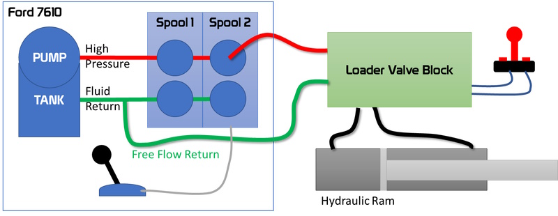
To make the loader easier to operate, I want to remove one of the levers by introducing a free flow return. Once installed, this arrangement will mean I still need to work two levers for some actions. However, it will massively simplify operations for most loader tasks. I don’t mind using my knee to move the feed lever when needed.
Where to fit the free flow return
If you ever needed evidence of farmers’ ingenuity and engineering skill, take a little time to Google ‘free flow return’ solutions for tractors. The internet is awash with cunning solutions and well-devised engineering approaches to this common problem. For the Ford 10 Series, the most common place to fit a free flow return connection is in the filler neck for the rear hydraulic oil. There is an example below, currently available at Neils Vintage Tractor Parts. Unfortunately, the age of my Ford 7610 means there is no filler neck to connect to.
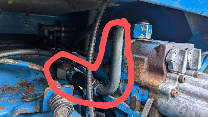
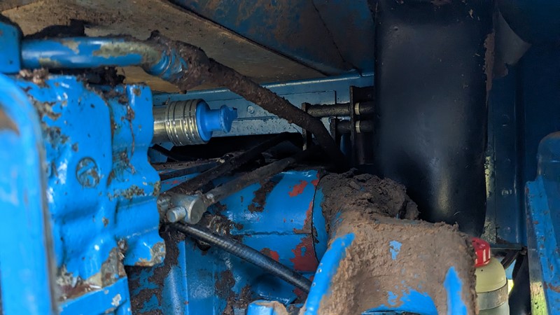
Perhaps the lack of filler neck isn’t a bad thing, as too much fluid reportedly pops the cap of the filler tube, sending oil everywhere! So instead, I will fit a free flow return into the pipe run shown below. This is a common solution with connections in the rubber pipe or brazed into the metal pipe from the top of the spool.
These are fine solutions. However, I want to be able to quickly take the loader off the tractor for shows and road runs, so I want to include a quick coupler. There are good arguments for and against this, but a quick coupler is my direction. I don’t want to fit the mass of the coupler into a flexible pipe section and risk fatiguing the joint. So I need something a bit more solid to attach to.
Solid fitting for the free flow return
To quickly remove the loader or fit another implement that needs a free flow return, I want the connector to the tractor to be a quick-release type. I’m not entirely convinced of this logic. If I need to remove the loader, the tractor brackets will stay behind with the valve block and pipes. That said, it’s a nice quick engineering challenge.
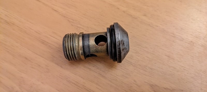
The most robust solution I could see was to mount a 1/2″ BSP fitting to the end of the bolt that holds the return banjo fitting to the tractor. Some searching suggests this is an easy bolt to replace should I cockup the welding. The banjo bolt was quickly removed after a really good clean-up around the area. I don’t need all that dirt getting in the oil!
Drilling out the banjo bolt
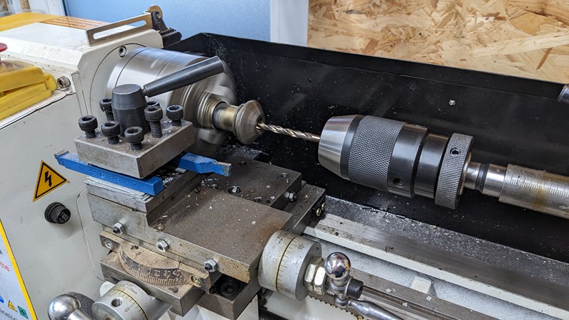
Back home, I can throw the bolt on the mini-lathe, centre and drill a hole through the middle. I start with a 4mm hole and slowly bore out to 8mm. Having measured up the rest of my hydraulic connectors, the smallest orifice is actually 8mm. Hopefully, 8mm won’t cause any notable fluid flow restriction.
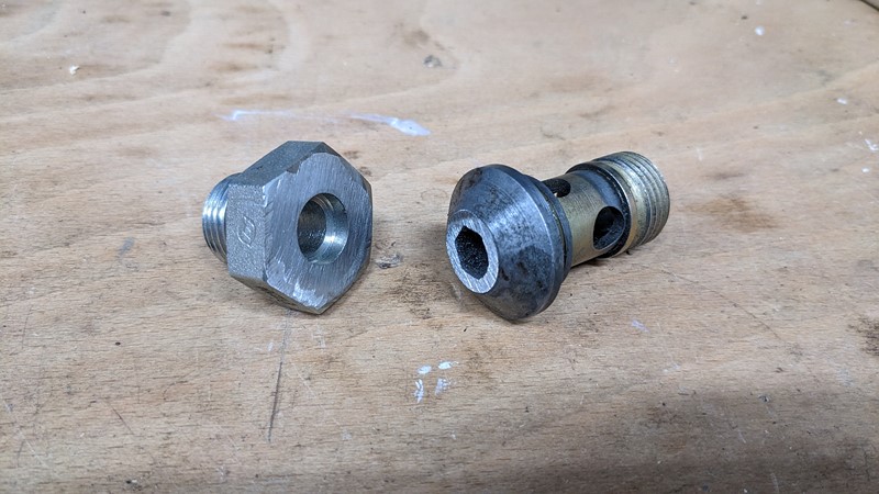
I couldn’t find a cheap boss to weld onto the banjo bolt. So instead, I’ve bought a 5/8″ to 1/2″ adapter and carefully cut the 5/8″ side off. Then a little time on the belt sander flattens off both the cut-down boss and the top of the banjo bolt.
Welding the two parts together
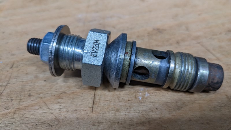
A long M8 cap head bolt and plenty of washers allow the boss and bolt to be aligned. Keeping them firmly in place during welding is important to maintain the hole. Given its purpose, I probably spent excessive time getting the two halves centred here, but there we go.
Out with the liquid metal glue gun to join the two parts. Plenty of heat and matched wire speed, and pretty quickly, the two halves are stuck together. I’m hopeful that the join isn’t porous. The two halves are certainly well stuck together. I guess time will tell if the joint is going to leak.
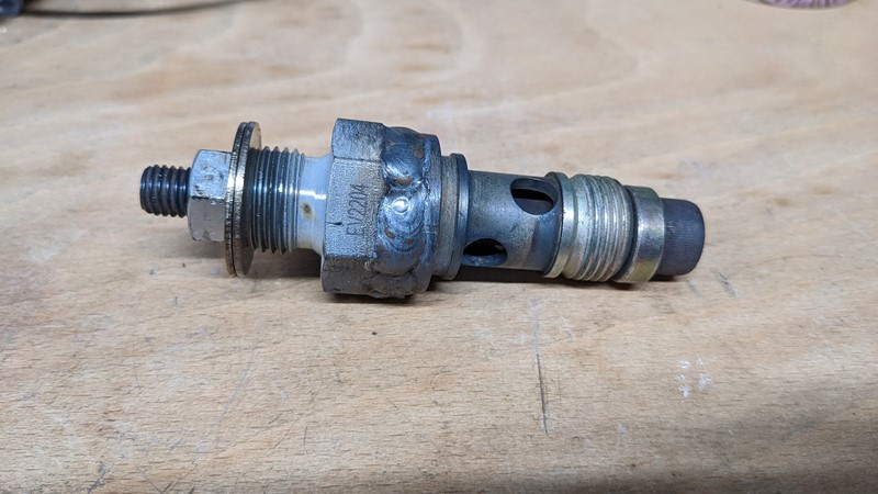
The final free flow return assembly
Once welded up and cooled, the weld is dressed a little. Flatting off the high spots is essentially to let a socket drop over the joint rather than aesthetics. When this modified return is installed on the tractor and covered in filth, the weld will be nearly invisible. I hope!
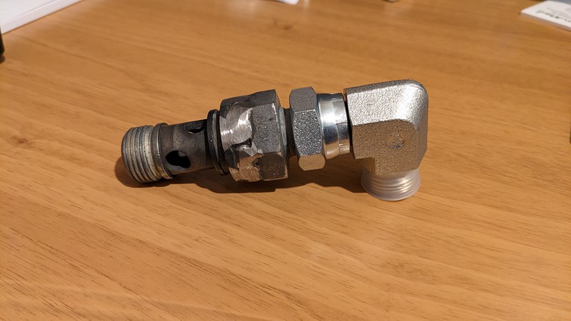
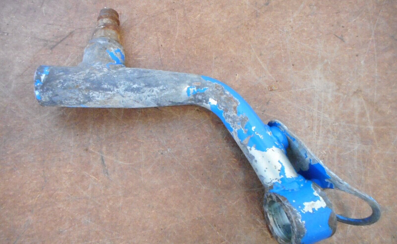
The final piece of the puzzle is the 90-degree swivel joint. This joint has the 8mm restriction, while most connections have a 10mm ID opening. Hopefully, the restriction won’t cause issues. I need the swivel to be able to aim the coupler in the right direction.
Installing the free flow return
Overall, I’ve probably spent more time travelling to and from the tractor than I have in making the modification. Of course, sometimes that’s the way with the tractor, but it has been a satisfying job. In total, the couplers cost about £20.
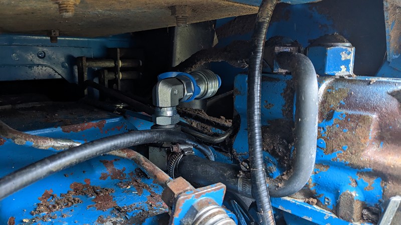
Installing the free flow return onto the tractor is straightforward. First, the banjo bolt with the adapter welded on is reinstalled with a suitable socket. Then the 90-degree swivel is installed. And finally, the quick-release coupling goes on.
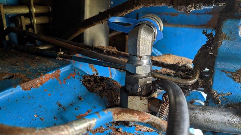
Once installed, the assembly looks pretty good. I definitely prefer this method over connecting to the flexible rubber pipe. A solid-feeling connector is much more satisfying to grab hold of than something soft and floppy.
Despite little consideration going into the final positioning, it’s come out really well. The quick connector outlet sits perfectly between the spool linkage and the hydraulic feed. I’d think it was a factory fit if I didn’t know better!
What’s next after the free flow return?
I’m more than happy with how the free flow return has come out. The existing pipes from the loader valve block fit perfectly. I can only assume the original installation must have had a free flow return in a similar place. Do I need the quick connector? Probably not. That said, the modification has turned out well, and several months later, it is working perfectly.
Now that I have the loader on and the hydraulics and controls working, I will need some implements. A loader bucket is high on the list, and I have my eye on a local one. Then I’ll probably need a counterweight to keep the load off the new spindles in the front axle. After that, a set of forks would be handy too. Hours on eBay suggest the world is my oyster for attachments. I can see plenty of opportunities for misadventure.
Back to eBay for me!
M
NEXT – Ford 7610 – Tractor Bucket
PREV – Ford 7610 – Fitting a Loader


[…] NEXT – Ford 7610 – Free Flow ReturnPREV – Ford 7610 – Service turns major […]
[…] NEXT –PREV – Ford 7610 – Free Flow Return […]